ROBERTS MECHANISM
Many engineering applications require directions to move in a linear fashion or “straight-line” motion. We can use a linear motion guide for the same that can direct a device accurately along a straight line
The Roberts linkage is a four-bar linkage which converts a rotational motion to approximate straight-line motion.
The linkage was developed by Richard Roberts (1789–1864). Richard Roberts was a Welsh patternmaker and engineer whose development of high-precision machine tools led to the origin of production engineering and mass production.
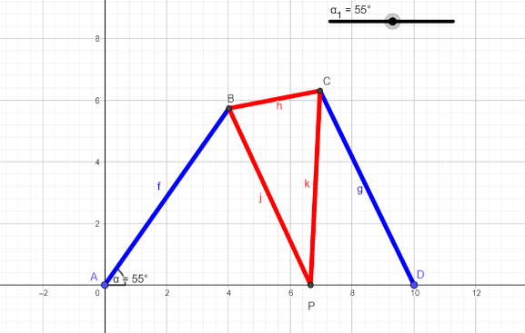
Roberts’ Straight-line Mechanism is symmetrical four bar linkage which is composed of a coupler extension joining the coupler mid-point. It is similar to the Triple Rocker Mechanism in which none of the links rotate completely. The line connecting the two adjacent joints is perpendicular to the coupler extension to form an isosceles. The coupler extension guides the coupler midpoint to a direction of an approximate straight-line motion without being driven by cranks or rockers.

If we look at the arrangement of the links in the above animation it consists of :
- Driver (Black Cross)
- Rocker (Yellow links)
- Triangular Coupler (Green links)
Dimensions Ratio:
The dimension of the Coupler are taken in the ratio of a , a , b (where a is the longer side) , the Rocker is in the ratio a , Horizontal Distance between the Driver is in the ratio 2b.
- If we consider the Triangular Coupler which is an isosceles triangle in which 2 sides are equal , the extended links are equal and is taken as 2 units and the base link is taken as 1.5 units.
- The Rocker i.e. the Yellow link is taken as 2 units.
- The distance between the Driver joints is taken as 3 units.
we can also consider the dimension given in figure 2 .

Number of Links:

Deep eye into the Mechanism:
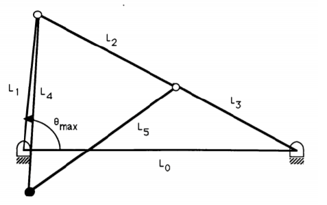
As we know Roberts’ Mechanism is a device that changes an oscillating input into a rough approximation of a straight line. The input can be applied at either Joint A or Joint E (fig 2), which is fixed to the ground. In the illustrations, the input is applied at Joint A. As it oscillates, it pushes the triangular coupler to the right, which is connected to a rocker anchored at Joint E. As the coupler moves to the left, the top of the coupler follows a path that is roughly a straight line.
So by how much angle the coupler went toward the right side i.e. the max and the minimum angle should be calculated to be get a better analysis of the mechanism.
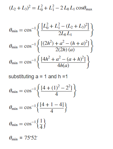
Minimum Angle:


Maximum Angle:
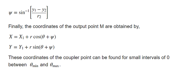
Position of the Moving Point:
The vector representation of a symmetrical Roberts Linkage is shown below in the figure 3.
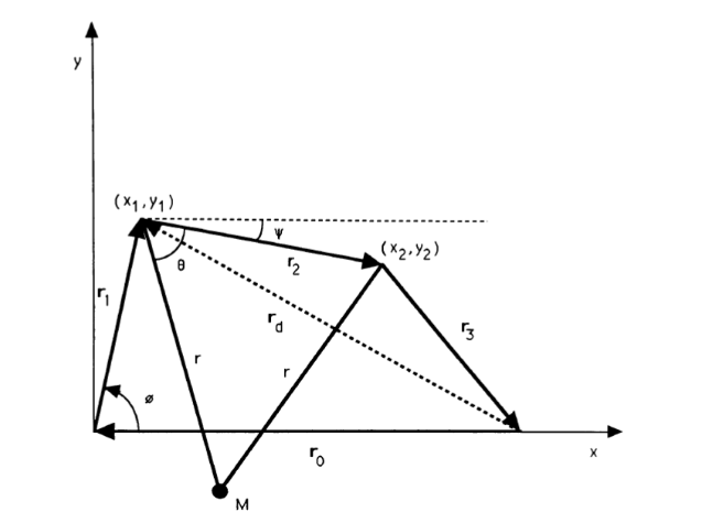
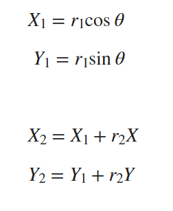
The coordinates (x1,y1) and (x2,y2) are calculated as follows:
Calculating coordinates of the point M(x, y) from the above figure by the cosine law:
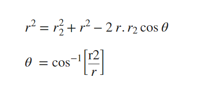
and the Angle :
Implementation
The implementation of this Robert’s Mechanism is done in GeoGebra and Python.
GeoGebra
GeoGebra is a dynamic mathematics software that combines various mathematical concepts such as geometry, algebra, spreadsheets, graphing, statistics, and calculus into one user-friendly program. It is designed for use by students of all levels and is widely used in STEM education to support teaching and learning methods worldwide. The GeoGebra community is rapidly growing and present in almost every country, making it the leading provider of dynamic mathematics software.
Python
The code file for the Implementation are available in my GitHub repository.
KS-prashanth/Roberts-Mechanism: Roberts Mechanism (github.com)